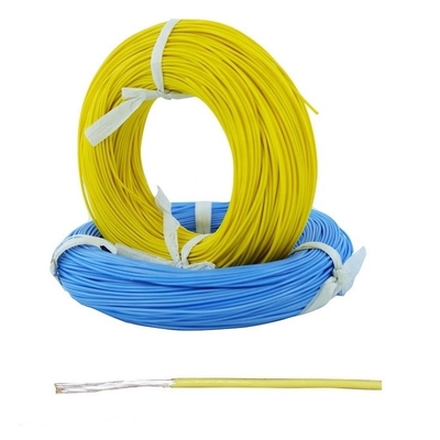
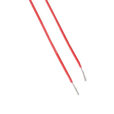
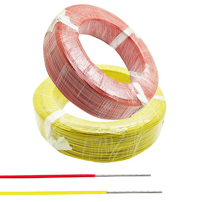
Resistance High Temperature high temperature PTFE Insulated Equipment Wire
About PTFE wire
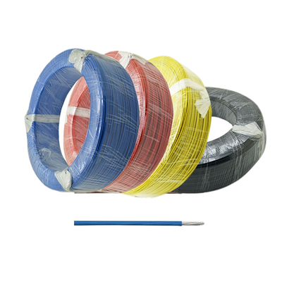
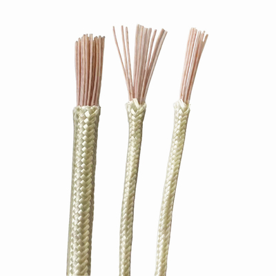
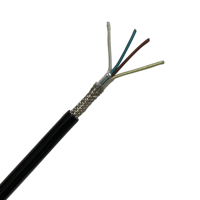
PTFE wires allow wiring systems to be used and operated in the most demanding of environments. PTFE is resistant to lubricants and fuels, very flexible, plus it has excellent thermal and electrical properties.
Applications of PTFE Wire
1. For connecting internal electrical equipment of various kinds of aircraft, airships, armored vehicles, ships under high temperature environment.
2. In industrial and mining enterprises such as metallurgy, petroleum, chemical and power plants, and is used as a connecting line for various electrical appliances, instruments and automatic devices under high temperature conditions and harsh environments
Properties of PTFE Wire
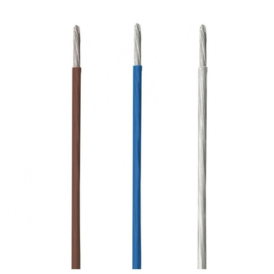
1. The conductor is made of 0.03-0.08mm copper wire or silver-plated copper wire wrapped by ptfe film
2. Core can be made: 1, 7, 19, 30, 42, 49, 75, 100
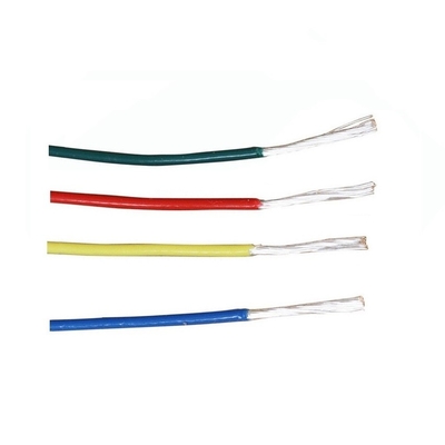
3. Color: black, brown, red, orange, yellow, green, blue, purple, gray, white
4. Long-term working temperature: copper core -60 ~ +200℃, silver-plated copper core -60 ~ +250℃
Conductor | Insulation thickness mm |
Wire outer diameter mm |
Resistance of insualtion | |||||||||
Nominal section area mm2 |
single wire x dia. | Conductor Dia. mm |
110V | 250V | 600V | AFR-250 type | AFRP-250 type | MΩ·km | ||||
mm | 110V | 250V | 600V | 110V | 250V | 600V | ||||||
0.013 | 7×0.05 | 0.15 | 0.1 | 0.15 | 0.25 | 0.38 | 0.49 | 0.71 | 0.7 | 0.82 | 1.02 | 5×10³ |
0.035 | 7×0.08 | 0.24 | 0.1 | 0.15 | 0.25 | 0.47 | 0.58 | 0.81 | 0.85 | 0.91 | 1.14 | |
0.06 | 7×0.10 | 0.3 | 0.1 | 0.15 | 0.25 | 0.55 | 0.65 | 0.87 | 0.9 | 0.97 | 1.2 | |
0.08 | 7×0.12 | 0.36 | 0.1 | 0.15 | 0.25 | 0.6 | 0.7 | 0.93 | 1 | 1.03 | 1.26 | |
19×0.07 | ||||||||||||
0.1 | 7×0.14 | 0.42 | 0.1 | 0.15 | 0.25 | 0.7 | 0.83 | 1 | 1.05 | 1.15 | 1.3 | |
19×0.08 | ||||||||||||
0.14 | 7×0.16 | 0.5 | 0.1 | 0.15 | 0.25 | 0.73 | 0.85 | 1.05 | 1.05 | 1.18 | 1.45 | |
19×0.10 | ||||||||||||
0.2 | 7×0.20 | 0.6 | 0.15 | 0.3 | 0.85 | 0.97 | 1.3 | 1.3 | 1.4 | 1.7 | ||
19×0.12 | ||||||||||||
0.35 | 7×0.25 | 0.8 | 0.15 | 0.3 | 1.2 | 1.5 | 1.6 | 1.9 | ||||
19×0.16 | ||||||||||||
0.5 | 7×0.30 | 0.9 | 0.15 | 0.3 | 1.3 | 1.6 | 1.7 | 2 | ||||
19×0.18 | ||||||||||||
0.8 | 7×0.37 | 1.1 | 0.2 | 0.3 | 1.65 | 1.85 | 2.05 | 2.3 | ||||
19×0.23 | ||||||||||||
1 | 19×0.26 | 1.3 | 0.2 | 0.3 | 1.88 | 2 | 2.25 | 2.45 | ||||
1.2 | 19×0.28 | 1.4 | 0.2 | 0.3 | 1.95 | 2.15 | 2.38 | 2.55 | ||||
1.5 | 19×0.32 | 1.6 | 0.2 | 0.3 | 2.15 | 2.35 | 2.63 | 2.83 | ||||
2 | 19×0.37 | 1.85 | 0.2 | 0.3 | 2.4 | 2.6 | 2.97 | 3.08 | ||||
2.5 | 19×0.14 | 2.34 | 0.2 | 0.35 | 2.95 | 3.2 | 3.43 | |||||
49×0.26 | ||||||||||||
3 | 49×0.28 | 2.52 | 0.2 | 0.35 | 3.1 | 3.37 | 3.5 | |||||
4 | 49×0.32 | 2.88 | 0.35 | 3.52 | 4.12 | |||||||
6 | 49×0.39 | 3.51 | 0.35 | 4.15 | 4.75 |
Noted:Specification and core no. are not limited to above regulation,they could be customized.